System Overview
Purpose of a Modular Truss Stage System
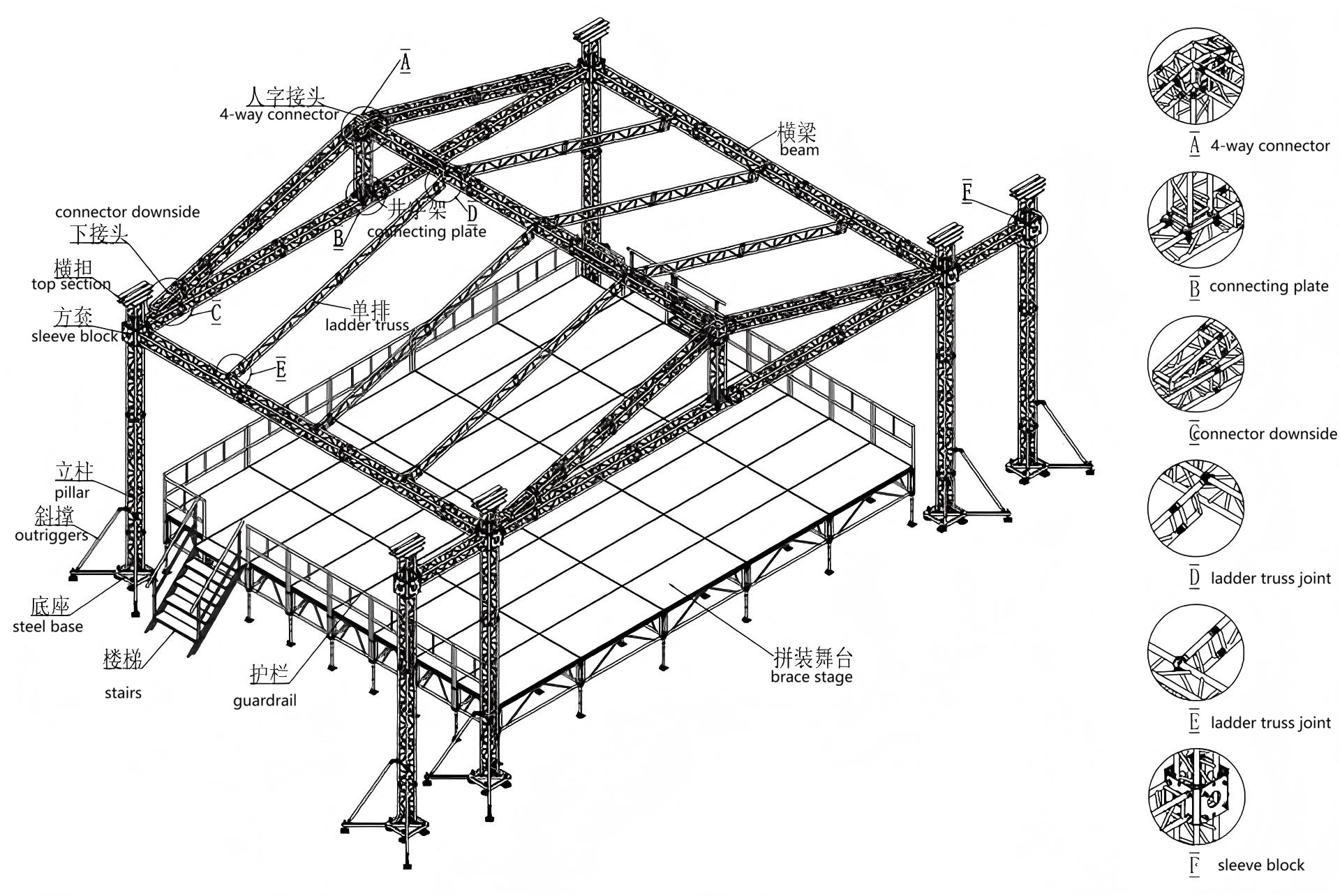
A modular truss stage system is a temporary yet load-bearing structure widely used for outdoor events and concerts that require a roofing system. Such systems are typically applied in medium-scale applications where controlled span and height are required for performance, lighting, and sound integration.
The roofing structure commonly consists of a combination of 290×290 mm spigot truss and 290 mm ladder truss, forming the primary support framework for roof covers and suspended equipment. Beams and vertical pillars are also commonly constructed using 290×290 mm box truss elements.
Although the overall layout may appear asymmetrical to accommodate lighting and sound equipment, load distribution is balanced through structural arrangement and component interaction to achieve on-site stability and functional requirements.
Primary Load-Bearing Components
Vertical Pillars (Pillars / Towers)
Pillars are the primary vertical load-bearing elements connecting the roof structure to the ground. They enable the truss system to be lifted from ground level and support elevated equipment such as lighting and audio systems. Loads from the upper structure are transferred vertically through the pillars to the base system.
Steel bases serve as the interface between the truss system and the ground. Their role is to distribute loads into the supporting surface and provide a stable foundation for the entire structure.
Outriggers are auxiliary stabilizing elements installed between the pillars and the base. Their primary function is to enhance lateral stability by transferring forces along an inclined path into the ground, expanding the effective contact area and reducing stress concentration at the base. Outriggers are functional structural components rather than decorative accessories.
Common errors:
Underestimating the role of outriggers and base footings
While increased ground contact area is often recognized, the stabilizing function of outriggers is sometimes overlooked. Properly installed outriggers help distribute loads more evenly and reduce localized stress, significantly improving overall structural stability, particularly under lateral forces such as wind.
Assuming a fixed installation angle
Outriggers are generally installed at an inclined angle to improve force transfer efficiency. However, the actual angle should be determined based on system height, site conditions, and stability requirements rather than assumed as a fixed value.
Beams & Roof Truss
The beam system, commonly constructed using 290×290 mm box truss, is designed for long-span applications and higher distributed loads. As span length increases, deflection control becomes an important consideration and must be evaluated as part of the overall system design.
The ladder truss, typically 290 mm in height, is primarily used as a roof-supporting member for lightweight roofing materials such as canvas covers. Its lower self-weight makes it suitable for applications where reduced roof load and easier handling are desired.
Ladder Truss vs. Box Truss
Compared with box truss, ladder truss has a lower self-weight, making it advantageous when minimizing roof load is a priority. Its lighter structure also improves handling efficiency during installation and transportation. Box truss, by contrast, provides higher structural stiffness and is more suitable for longer spans or applications requiring greater load-bearing capacity. Selection between the two should be based on structural requirements rather than convenience alone.
Connection & Node Components
4-Way Connector
4-way connectors are installed at key positions at the top of the roofing structure to form the gable roof geometry. These connectors serve as multi-directional load transfer nodes, redistributing forces from the roof apex toward the roof edges and front beams.
As fixed-angle welded components, 4-way connectors are designed to work within predefined geometric limits. They should not be used for forced angle adjustments or super-angle splicing, as this may introduce unintended stress and compromise structural integrity.
Symmetrical placement of connectors at the front and rear of the structure helps maintain balance and improves overall roof stability under external forces such as wind or suspended loads.
Connecting Plate(Connecting Plate)
Connecting plates are used to link roof truss pillars with horizontal beam elements. Their primary function is force redistribution, allowing loads from the roof structure to be transferred smoothly into the main truss frame.
By stabilizing the connection between roof beams and supporting pillars, connecting plates play a critical role in maintaining structural continuity rather than simply acting as passive connectors.
Connector Downside
Connector downside components are positioned at the lower end of gable roof trusses, forming the transition between roof elements and horizontal beams. They guide loads from the roof structure into the beam system and ensure proper alignment between different truss sections.
These connectors are designed with a uniform orientation, provided that the bottom surface is correctly seated on the beam to ensure effective load transfer.
Auxiliary & Stabilizing Components
Sleeve Block
Sleeve blocks are vertical connection joints between pillars and beams, commonly used in systems requiring height adjustment through manual hoists or chain motors. In addition to enabling vertical movement, sleeve blocks play a critical role in maintaining alignment during lifting operations.
Installation risks:
Improper locking
Failure to fully secure locking mechanisms can interrupt load transfer from the roof structure to the pillars, creating instability during lifting or operation.
Mixing incompatible sleeve block types
Using different sleeve block designs within the same system may lead to uneven load paths and reduced reliability. Compatibility and regular inspection are essential for maintaining system integrity.
Outriggers
Outriggers are stabilizing components rather than primary load-bearing elements. Their purpose is to enhance lateral stability and reduce the risk of overturning caused by wind, uneven loading, or dynamic movement. Proper placement and secure installation are essential to ensure effective stabilization.
Stage & Access Components
Brace stage systems are widely used due to their structural stability and load-handling capability. Their modular design allows for flexible configuration while maintaining a high level of safety during performance use.
Guardrails and stair handrails are essential safety components, designed to protect performers and crew during operation. These elements should be considered part of the overall system rather than optional accessories.
Stairs are typically height-adjustable to match varying stage elevations and must provide secure, slip-resistant access under different operating conditions.
Stage components must be considered as part of the structural system, not independent accessories.
Component Interaction & System Integrity
A common misconception is that the use of individually proven components automatically results in a safe structure. In reality, system safety depends on how components interact and how forces are transferred throughout the structure.
Typical risk scenarios include:
Strong beam combined with weak joint or connector
Disparity in component capacity can lead to stress concentration at connection points, increasing the likelihood of joint failure.
Sturdy pillar combined with insufficient base support
Even a robust vertical element can become unstable if its foundation lacks adequate strength or contact area.
For load calculation principles and system verification methodologies, please refer to our Load Analysis documentation.