Understanding Load Paths from LED Screens, Line Arrays, Lighting Systems and Temporary Structures to the Ground
A large stadium concert stage may appear to be a collection of visual elements:
Giant LED screens.
Powerful line array speakers.
Complex lighting systems.
Large roof structures.
Audience platforms.
FOH towers.
Relay speaker towers.
However, from an engineering perspective, the most important question is not only how these components are installed, but:
How are the loads created by these heavy systems transferred safely through temporary structures and finally into the ground?
During the construction of the 2026 Guangzhou Pearl Beer Festival Music Festival, many different heavy systems were integrated into one temporary event infrastructure.
The project included:
A hydraulic main-stage roof.
Large Ringlock structures.
Multiple LED walls.
Suspended line-array systems.
Large lighting trusses.
FOH control structures.
Relay speaker towers.
Temporary stage systems.
Each component created different types of loads.
Some created mainly vertical loads.
Some created dynamic loads.
Some created overturning forces caused by wind or suspended equipment.
A safe concert structure depends on understanding the complete load path.
The engineering principle can be summarized as:
Equipment

↓

Support Structure

↓

Primary Structure

↓

Base System

↓

Ground Protection

↓

Existing Stadium Surface
The equipment itself is only the beginning of the load system.
What Are the Major Heavy Loads in a Stadium Concert?
A stadium concert contains many large components, but their structural requirements are different.
The same support method cannot be used everywhere.
Equipment
Location
Approximate Scale
Main Support Method
Main LED Screen
Rear of main stage
20m × 16m
Stage platform
Side LED Screens
Both sides of stage
Each 20m × 16m
Ringlock structure
FOH LED Screens
Audience area
14m × 10m
FOH Ringlock structure
Main Line Array
Front of stage
16 cabinets per side
Apron cantilever beam
Relay Speaker Tower
Stadium center
12 cabinets per side
Independent tower structure
Moving Beam Lighting
Curved stage trusses
36 units
Aluminium curved truss
Strobe Lighting
Curved stage trusses
36 units
Aluminium curved truss
Roof Lighting
Main roof truss
4 groups
Roof rigging system
Hoisting Motors
Roof system
42 motors
Roof structure
This table shows an important engineering principle:
The heavier the equipment is, the more important the support path becomes.
A 10-ton LED wall and a 10-ton speaker system do not necessarily require the same structural solution.
The location, height, wind exposure and dynamic behaviour determine the correct design.
Understanding Load Paths in Temporary Concert Structures
In permanent buildings, loads are usually transferred through columns, beams and foundations.
Temporary event structures follow the same engineering logic, but the systems are modular and removable.
Every load must have a controlled path.
For example:
LED Load Path
LED Cabinet

↓

Support Beam

↓

Ringlock / Stage Structure

↓

Base Plate + Adjustable Jack

↓

Ground Protection

↓

Stadium Surface
Line Array Load Path
Speaker System

↓

Rigging Hardware

↓

Truss / Beam

↓

Main Structural Frame

↓

Base System

↓

Ground
Ballast Load Path
Water Tank

↓

Support Platform

↓

Ringlock Ledger System

↓

Vertical Standard

↓

Base Jack

↓

Ground Protection
The purpose of engineering is not only to support weight.
It is to control where the weight travels.
How Are Large LED Screen Loads Managed?
Large LED screens are among the most visible heavy loads in a concert venue.
However, different LED locations require different structural solutions.
During this project, three different LED support methods were observed.
Main Stage Background LED Screen
The main background LED screen was approximately:
Width: 20m
Height: 16m
Unlike suspended LED systems, this screen was installed directly on the main stage platform.
Its load path was:
LED Cabinet

↓

Stage Support System

↓

Stage Deck

↓

Ringlock Stage Structure

↓

Base System

↓

Ground
This method has several advantages:
Shorter load transfer path.
Easier maintenance.
Reduced roof loading.
Better stability for a large rear screen.
The main LED does not need to be supported by the roof because the stage itself provides a direct structural platform.
Side LED Screens on Ringlock Structures
The two side LED structures were significantly different.
Each side was approximately:
Width: 20m
Height: 16m
They were installed on large Ringlock structures.
The observed side Ringlock dimensions were approximately:
Height: 21m
Width: 24m
Depth: 6m
These Ringlock systems were not simple screen holders.
They also supported:
Line arrays.
Lighting equipment.
Maintenance access.
Technical working areas.
The load path became:
LED Screen

↓

Steel Square Tube Support Beam

↓

Ringlock Ledger

↓

Ringlock Standard

↓

Base Plate

↓

Adjustable Jack

↓

Ground Protection
The steel square tubes at the bottom of the LED structure were used to:
Level the LED cabinets.
Distribute the cabinet load.
Reduce alignment errors.
The installation logic of LED screens on Ringlock structures is discussed further in:
On grass areas, additional modular plastic flooring was used.
The purpose was:
Load distribution.
Surface protection.
Stable working conditions.
Reduced point pressure.
A structure may be strong enough, but if the ground beneath cannot receive the load safely, the entire system becomes unsafe.
How Are Stage Deck Loads Managed?
The main stage itself is also a heavy load system.
Observed stage height:
Approximately 2 metres.
The structure followed a standard Ringlock stage configuration with:
Vertical supports.
Cross braces.
Base adjustment systems.
The load path:
Stage Surface

↓

Deck Frame

↓

Ringlock Support

↓

Cross Bracing

↓

Base Jack

↓

Ground Protection
The stage must support:
Performers.
Instruments.
Equipment.
LED systems.
Moving loads.
Why Can’t Heavy Equipment Be Placed Anywhere?
One of the biggest misunderstandings about event construction is:
If the structure is strong, why not put the equipment anywhere?
Because strength alone is not enough.
Engineers must consider:
Load Location
A 1-ton load in the centre of a structure is different from a 1-ton load at the edge.
Load Concentration
A small contact area creates higher local pressure.
Structural Connection
The load must enter through designed members.
Ground Condition
The surface below must also receive the load.
Stability
Some loads create overturning forces rather than only downward pressure.
For example:
A water tank.
A speaker tower.
A suspended LED frame.
All require different solutions.
Engineering Trade-Offs in Heavy Load Management
Large event structures always involve balancing different requirements.
Engineering Choice
Purpose
Aluminium roof system
Reduce dead load while maintaining strength
Ringlock structure
Flexible high-capacity modular support
Steel support beams
Improve LED alignment and load distribution
Ballast tanks
Increase stability against movement
Ground protection system
Protect stadium surface and distribute pressure
Adjustable bases
Correct uneven ground conditions
The goal is not to make every component stronger.
The goal is to create a complete, balanced system.
Conclusion
Heavy equipment management is one of the most important parts of large concert engineering.
The challenge is not simply supporting weight.
It is controlling how every load travels:
From:
LED cabinets.
Speakers.
Lighting fixtures.
Roof systems.
Platforms.
Ballast tanks.
Through:
Trusses.
Ringlock structures.
Beams.
Columns.
Base systems.
Into:
Ground protection.
Stadium surfaces.
A successful temporary concert structure is therefore not built by adding stronger components randomly.
It is created by designing a complete load-transfer system.
In large event engineering, safety does not come from one strong element. It comes from every load having a clear and controlled path from equipment to ground.
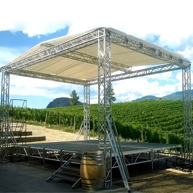
The DragonStage 11x6x7m Covered Concert Roof Truss System combines an 11m-wide × 6m-deep × 7m-high main stage roof with two 2m side PA speaker wings.
The illustrated configuration features a pitched aluminum roof framework with a blue roof canopy, four main support towers, two independent speaker towers, and a matching modular stage platform with guardrails and dual stair access.
Designed for concerts, festivals, live performances, community events, and temporary outdoor productions requiring a coordinated stage roof and separate speaker-support positions.
The DragonStage 10x5x7m Aluminum Pitched Roof Truss System is a modular concert-stage structure featuring a 10m-wide × 5m-deep × 7m-high main roof frame with 2m side speaker wings on both sides.
The configuration combines a pitched aluminum roof-truss framework, four main support towers, two additional side speaker towers, and a matching modular stage platform as illustrated. It is designed for concerts, festivals, live performances, community events, and temporary stage productions requiring separate side positions for line-array or PA equipment.
The DragonStage 32x24x18m Large Ringlock Scaffold Roof Truss Structure combines a large modular Ringlock support system with a heavy-duty aluminum pitched-roof truss framework.
Designed for stadium-scale ceremonies, festivals, cultural performances and large outdoor event productions, the system integrates extensive scaffold support zones, heavy aluminum roof trusses, custom roof connectors, tensioning components and a large roof canopy.
The drawing identifies a nominal 32m × 24m × 18m configuration, with the overall height shown at approximately 18.21m.
A complete professional event sound package combining 16 dual-12-inch passive line array speakers, 10 dual-18-inch subwoofers, 6 stage monitors, dedicated Class-D power amplifiers, dual 4-in/8-out DSP processors, power management, wireless microphones, rigging frames, flight cases, amplifier racks and cabling.
This system is designed for concerts, live performances, festivals, touring productions and other professional event sound applications where the customer needs a coordinated PA package rather than individual speakers.
For other professional audio systems, see Stage Sound.
The DragonStage 15×10×8m Aluminum Curved Roof Truss System is a modular concert-stage roofing structure featuring a curved overhead truss framework, four main support towers, and two additional side-wing towers.
The system uses CS389×389mm and CS289×289mm aluminum spigot truss, sleeve block assemblies, BA05 manual hoists, tower bases, outriggers, and a PVC roof canopy. The side wings extend the configuration for additional event-production arrangements, subject to the final equipment layout and verified loading requirements.
Designed for concerts, music festivals, touring productions, and temporary entertainment stages, this system can be supplied with matching modular stage platforms and accessories.
Custom Star Shape Truss Aluminum for Wedding Decoration Art Design
Pentagram,five-pointed star
The DragonStage Custom Five-Point Star Aluminum Truss is a decorative event structure designed for wedding backdrops, stage displays, photo areas, exhibition decoration, and artistic event installations.
Featuring a distinctive pentagram-style star shape, the product is available in 2.5×2.63m, 3×3.15m, and 4×3.8m configurations, with selected 200mm and 300mm truss section options.
The customized star geometry provides an alternative to conventional square, rectangular, or circular event truss structures.
The DragonStage 9x6m Bolt Truss Gantry System is a modular event-support structure featuring two vertical truss towers, a horizontal bolt-connected truss beam, tower-head assemblies, base plates, and diagonal outrigger bracing.
With a nominal horizontal dimension of 9m (29.5ft) and a height of 6m (19.7ft), this open-frame structure is intended for event lighting, stage production, backdrop framing, and temporary gantry applications. Final truss specifications, support arrangements, and equipment loads are confirmed according to the project requirements.
The DragonStage 36x18x12m Large Concert Stage Roof Truss System is a large-format modular event structure featuring a multi-tower truss support system, an elevated overhead truss framework, and a modular stage platform with guardrails and stair access.
With nominal dimensions of 36m wide × 18m deep × 12m high (120ft × 60ft × 40ft), this configuration is intended for large concerts, music festivals, live performances, and temporary entertainment productions requiring an extensive stage area and overhead structural framework.
The DragonStage 6.72x4.89m modular event stage combines a 0.6m-high red stage platform with a 7.7m-wide, 4.4m-high rear box truss gantry. The open-top configuration provides a raised performance area and a separate overhead truss frame for event backdrop and production applications. Suitable for concerts, school performances, ceremonies, and indoor events, with final accessories and rigging requirements confirmed according to the project.
The DragonStage 25x10m Ringlock Grandstand is a large modular spectator-seating system designed for temporary sports events, school competitions, festivals, public performances, and other audience gatherings. Measuring 25m wide × 10m deep, the illustrated configuration features tiered seating, two access aisles, and three-sided guardrails. The specified main height is 2.5m, with an overall height of 3.5m. The modular Ringlock system can be configured according to the required seating layout, access arrangement, and project conditions.
A heavy duty iron adjustable clamp specifically designed for use in clear span marquees using grooved aluminium kader style beams. It has M10, M12 and M14 tapped mounting points.
Our professional Aluminum Alloy Spigot Square Truss is the industry standard for high-performance rigging. Designed with a robust modular system logic, this versatile solution is perfect for concert and event stages. It offers exceptional load-bearing stability and a sleek finish for supporting professional lighting and LED screens.
Section:Square200x200mm inclined tube: 12x2.0mm Main tube: 30x2.0mm Length:0.5/1/2/2.5m Braces: 20x2.0mm
This premium 200x200mm Aluminum Spigot Box Truss offers a compact yet incredibly strong structural solution. Ideal for exhibitions and trade shows, its high-precision conical connection system ensures rapid assembly. It is the perfect professional choice for creating sophisticated lighting truss grids in any concert and event stage environment.
Our 290mm Aluminum Square Spigot Truss with 50x3mm main tubing is a heavy-duty solution for professional rigging. Utilizing a modular system logic, this versatile series is ideal for concert and event stages, offering exceptional load-bearing stability and rapid assembly for any production environment.
The Dragonstage Aluminum Spigot 520x520mm Square Box 6 Ways Corner Truss Cube Connector is a device for constructing large, sturdy structures that are sturdy and lightweight. This device is made of aluminum, which is durable and lightweight. The product has a size of 520x520mm and can be used for building structures in 6 different ways. It also comes with two pieces of aluminum screws for assembling the structure. The device is able to withstand high pressure, so it is perfect for heavy objects.
This box can be used to create a stable structure for your display or party. You can use this box to create a corner truss cube. It can be used for exhibitions, retail, and party displays. The box has a 400x400mm or 389x389mm square opening. The box has six ways to connect.
Dragonstage Aluminum Spigot 300x300mm / 289x289mm Square Box 6 Ways Corner Truss Cube Connector is an aluminum spigot with a 300x300mm square box with 6 ways corner truss cube connector. This aluminum spigot is perfect for hanging lights, air conditioning, and other things. The dimensions of the spigot are 300x300mm square box with 6 ways corner truss cube connector.
Aluminum Spigot Truss Aluminum Base Plate with Handles 300mm 400mm 500mm 600mm 800mm with half conical and pins clips.
The DragonStage Aluminum Spigot Truss Base Plate with Handles is available in five square sizes from 300×300mm to 800×800mm, all using an 8mm-thick aluminum plate. Each configuration can be supplied with compatible half conical connectors, connector pins and R-clips for spigot truss installation. Integrated handles make the plates more practical to carry and position during repeated event setup and teardown.
this is 100x100x3mm base plate for f14 truss mini, with 4 half connectors and pins clips.
The DragonStage F14 Mini Truss Square Base Plate is a compact 100 × 100 × 3mm base plate supplied with 4 half conical connectors, connector pins and R-clips for compatible F14 mini truss systems. It is designed as a small mounting and connection accessory for exhibition, display, DJ, decorative and lightweight mini-truss applications.
Section:Square400x500mm Inclined tube: 25x2.0mm Main tube:50x3.0mm Braces:50x2.0mm Material: Aluminum 6061-T6
Our high-strength 500x400mm lighting truss is engineered from premium aluminum alloy for superior load-bearing performance. Ideal for music and audio setups, this durable screw-connection system ensures stability for professional stage environments. Built to meet rigorous safety standards, it provides a reliable foundation for any event production.
Section:Square500x500mm Inclined tube: 25x2.0mm Main tube:50x3.0mm Braces:50x2.0mm Material: Aluminum 6061-T6 This heavy-duty 500x500mm bolt aluminum square truss is the ultimate foundation for outdoor concert stages and large-scale events. Engineered for maximum structural stability, this aluminum truss system provides the high-load capacity needed to support massive lighting rigs and heavy audio arrays safely in any environment.
Section:Square400x400mm Inclined tube: 25x2.0mm Main tube:50x3.0mm Braces:50x2.0mm Material: Aluminum 6061-T6
This versatile 400x400mm aluminum roof screw lighting truss is the industry standard for medium-to-heavy stage rigging. Engineered for exceptional durability, this high-performance aluminum truss system supports heavy lighting and audio equipment with ease. It is the perfect foundation for building safe, professional modular stage systems for any event.
The DragonStage 4.88x2.44m Adjustable Outdoor Event Stage is a compact 16x8ft temporary platform with two access stairs and an adjustable height of 0.6–1.0m. It is designed for community events, ceremonies, school performances, church activities, DJ shows, presentations, and other temporary indoor or outdoor applications where a medium-size stage with flexible access is required.
Park Aluminum Portable Square Stage 8.54x6.1m 28x20ft Height: 0.8-1m
The DragonStage 8.54x6.1m Aluminum Park & Community Event Stage is a 28x20ft brace-supported modular platform built from 35 standard 4x4ft stage decks. The complete configuration includes 18mm anti-slip plywood decking, adjustable support stands, three-side guardrails, a 4-step stair, and black stage skirting, making it suitable for community concerts, park events, ceremonies, public performances, school activities, and temporary outdoor stages.
The Concert Custom Adjustable Portable Stage is the perfect addition to any concert venue. The Concert Custom Adjustable Cheap Portable Stage is a portable stage that is lightweight and easy to set up. It can be adjusted to the height of the performer and is available in two different colors. The Concert Custom Adjustable Cheap Portable Stage is made of durable, lightweight aluminum that will last for years to come. It has a black aluminum top with four black steel legs. The Concert Custom Adjustable Cheap Portable Stage is very easy to set up and is very stable.
Aluminum Mini Modular Stage Panel Flooring Systems 2.44x2.44m 8x8ft Height 0.6-1m with 1 stair.
The DragonStage 2.44x2.44m Adjustable Aluminum Modular Stage is a compact 8x8ft brace-supported event platform built from two standard 4x8ft / 1.22x2.44m wooden-topped stage panels. With an adjustable finished height of 0.6-1.0m, extendable support stands, stage braces, adjustable bases, and stair access components, it is suitable for small performances, DJ events, ceremonies, church activities, presentations, and temporary event staging.
Assemble Portable Stage Movable Aluminum Stage for Outdoor Concert Event 2.44x1.22m 8x4ft with 1 stair.
The DragonStage 2.44x1.22m Portable Aluminum Stage Kit is a compact 8x4ft temporary event platform supplied with one access stair. Designed for small outdoor concerts, DJ performances, speeches, ceremonies, promotions, and temporary event use, the modular stage can also be combined with additional compatible 4x8ft units when a larger platform is required.
The DragonStage 3.8x3.4m Aluminum Arch Truss Gateway is a compact curved entrance structure built from 290×290mm spigot truss with 300×500mm base plates. With overall external dimensions of approximately 3800mm wide × 3400mm high, it is designed for wedding entrances, exhibition gateways, red-carpet areas, event decoration, photo zones, and other temporary event displays.
Base plate only for the U-Frame 50. LED cans and moving heads can be installed freeriding in the room. In combination with the optional wheels the U-Frame Dolly will be an indispensable element on stages and show acts.
U-frame Truss And Dolly, it is custom U torm trusses (660 × 500 × 50mm) for 4 (4 utorm trusses+ top bar+ dolly) and 5 (4 utorm trusses+ top bar+ dolly) Robots in black color.
the dolly is made of 1.2x0.6m aluminum plate, thickness 8mm and 4 casters.
The DragonStage 5.49x1.22m Straight Aluminum Event Stage Ramp provides a direct access route for wedding stages, corporate events, ceremonies, hotel functions, and other temporary platforms. The ramp measures approximately 18ft long × 4ft wide (5.49 × 1.22m) and uses modular 4 × 4ft / 1.22 × 1.22m deck sections with 1m / 3.28ft high guardrails along both sides.
The DragonStage 3.0x1.22m Compact Aluminum Stage Transition Ramp provides a short, direct access route between ground level and temporary event stages. With an overall length of approximately 3.0m / 9.84ftand a width of approximately 1.22m / 4ft, the ramp uses modular aluminum stage components and includes 1m / 3.28ft high guardrailson both sides.
The DragonStage 7.84x1.23m Narrow Straight Aluminum Stage Access Ramp provides a direct route between ground level and an elevated temporary stage for performers, speakers, technicians, event staff, and production crew. Its slim footprint measures approximately 308⅝ × 48⅜ in (7.84 × 1.23m)and uses modular 4 × 4 ft / 1.22 × 1.22mramp deck sections with 1m / 3.28ft high guardrailsalong both sides.
The DragonStage 10.30x1.63m Straight Aluminum Stage Production Loading Ramp provides a direct access route between ground level and temporary event stages. With an overall external size of approximately 405½ × 64⅛ in (10.30 × 1.63m), the system uses standard 4 × 4 ft / 1.22 × 1.22m modular deck sections and 1m / 3.28ft high guardrails along both sides. It is suitable for road cases, AV equipment, production carts, technicians, and general backstage stage access.
The DragonStage 7.32x3.05m Compact Switchback Aluminum Stage Service Ramp provides a continuous access route for AV carts, production trolleys, touring equipment, technicians, and stage crew. Its compact U-shaped footprint measures approximately 24 × 10 ft (7.32 × 3.05m)and uses standard 4 × 4 ft / 1.22 × 1.22mmodular ramp decks with 1m / 3.28ft high guardrailsalong both sides.
The DragonStage 7.40x8.26m L-Shaped Aluminum Backstage Loading Ramp is designed for moving flight cases, lighting cases, audio equipment carts, cable boxes, production trolleys, and event equipment between ground level and temporary stages. The 90-degree layout has an overall footprint of approximately 291⅜ in × 325¼ in (7.40m × 8.26m) and uses standard 4 × 4 ft / 1.22 × 1.22m modular deck sections with 1m / 3.28ft high guardrails along both sides.
The DragonStage 9.82x3.23m Switchback Modular Aluminum Event Stage Ramp is designed for temporary stages requiring a continuous access route for wheelchairs, performers, event staff, carts, and wheeled concert equipment. The compact U-shaped layout measures approximately 386⅝ in × 127¼ in (9.82m × 3.23m) and uses standard 4 × 4 ft / 1.22 × 1.22m modular ramp deck sections with 1m / 3.28ft high guardrails along both sides.